Model structure#
In this section all the hydrological model structures that can be used will be presented.
There are 4 different structures available:
- “gr-a”
4 parameters and 3 states structure derived from the GR model.
- “gr-b”
4 parameters and 4 states structure derived from the GR model.
- “gr-c”
5 parameters and 5 states structure derived from the GR model.
- “gr-d”
3 parameters and 3 states structure derived from the GR model.
Note
see the Math / Num Documentation for more information about GR model and scientific references.
Model structure description#
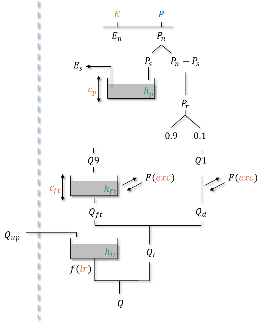
gr-a#
Parameters#
cp: the maximum capacity of the production storage \((mm)\),cft: the maximum capacity of the transfer storage \((mm)\),exc: the non-conservative exchange parameter \((mm/dt)\),lr: the linear routing parameter \((min)\).
States#
hp: the relative state of the production storage \((-)\),hft: the relative state of the transfer storage \((-)\),hlr: the absolute state of the routing storage \((mm)\).
Operating#
neutralization of \(P\) by \(E\) to determine a net rainfall \(P_n\) and a net evapotranspiration \(E_n\),
filling (resp. emptying) the production storage by \(P_s\) (resp. \(E_s\)),
splitting \(P_r\) into two branches, 90% filling the transfer storage and 10% into the direct branch,
application of the non-conservative flux \(F\) (which can be either positive or negative) in both branches,
summing \(Q_{ft}\), the outgoing flux of the transfer storage and \(Q_d\), the outgoing flux of the direct branch giving the cell flux \(Q_t\),
filling the routing storage by the upstream flux \(Q_{up}\),
computation of the final routed flow \(Q\) at the output of the routing storage.
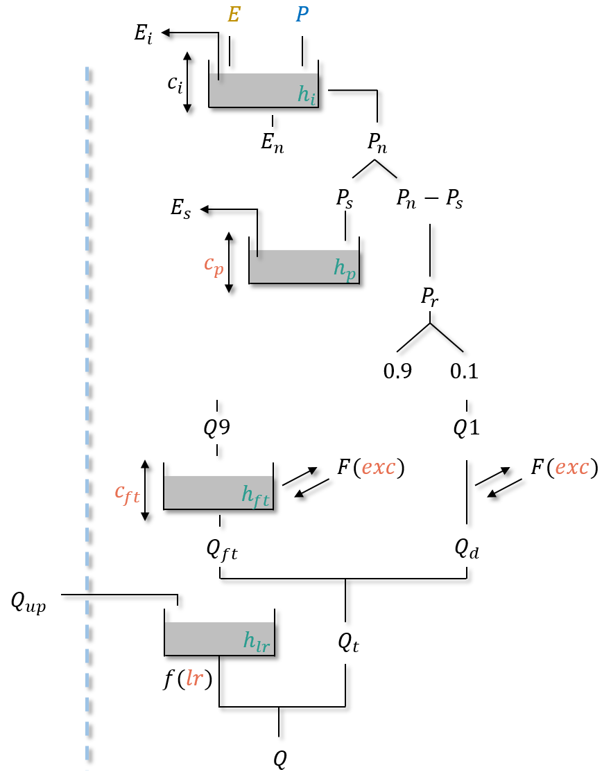
gr-b#
Parameters#
cp: the maximum capacity of the production storage \((mm)\),cft: the maximum capacity of the transfer storage \((mm)\),exc: the non-conservative exchange parameter \((mm/dt)\),lr: the linear routing parameter \((min)\).
States#
hi: the relative state of the interception storage \((-)\),hp: the relative state of the production storage \((-)\),hft: the relative state of the transfer storage \((-)\),hlr: the absolute state of the routing storage \((mm)\).
Operating#
neutralization of \(P\) by \(E\) to determine a net rainfall \(P_n\) and a net evapotranspiration \(E_n\) using an interception storage,
Note
In case of a daily time step simulation, the interception storage is disabled and the neutralization of \(P\) by \(E\) is similar to gr-a. Otherwise (at sub-daily time step), the maximum capacity \(c_i\) is adjusted to match fluxes between the simulation at daily time and sub-daily time step.
filling (resp. emptying) the production storage by \(P_s\) (resp. \(E_s\)),
splitting \(P_r\) into two branches, 90% filling the transfer storage and 10% into the direct branch,
application of the non-conservative flux \(F\) (which can be either positive or negative) in both branches,
summing \(Q_{ft}\), the outgoing flux of the transfer storage and \(Q_d\), the outgoing flux of the direct branch giving the cell flux \(Q_t\),
filling the routing storage by the upstream flux \(Q_{up}\),
computation of the final routed flow \(Q\) at the output of the routing storage.
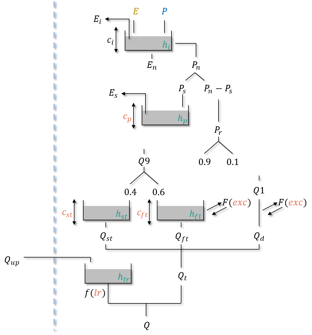
gr-c#
Parameters#
cp: the maximum capacity of the production storage \((mm)\),cft: the maximum capacity of the first transfer storage \((mm)\),cst: the maximum capacity of the second transfer storage \((mm)\),exc: the non-conservative exchange parameter \((mm/dt)\),lr: the linear routing parameter \((min)\).
States#
hi: the relative state of the interception storage \((-)\),hp: the relative state of the production storage \((-)\),hft: the relative state of the transfer storage \((-)\),hst: the relative state of the transfer storage \((-)\),hlr: the absolute state of the routing storage \((mm)\).
Operating#
neutralization of \(P\) by \(E\) to determine a net rainfall \(P_n\) and a net evapotranspiration \(E_n\) using an interception storage,
Note
In case of a daily time step simulation, the interception storage is disabled and the neutralization of \(P\) by \(E\) is similar to gr-a. Otherwise (at sub-daily time step), the maximum capacity \(c_i\) is adjusted to match fluxes between the simulation at daily time and sub-daily time step.
filling (resp. emptying) the production storage by \(P_s\) (resp. \(E_s\)),
splitting \(P_r\) into three branches, 54% filling the first transfer storage, 36% filling the second transfer storage and 10% into the direct branch,
application of the non-conservative flux \(F\) (which can be either positive or negative) in the first transfer and direct branches,
summing \(Q_{ft}\), the outgoing flux of the first transfer storage, \(Q_{st}\), the outgoing flux of the second transfer storage and \(Q_d\), the outgoing flux of the direct branch giving the cell flux \(Q_t\),
filling the routing storage by the upstream flux \(Q_{up}\),
computation of the final routed flow \(Q\) at the output of the routing storage.
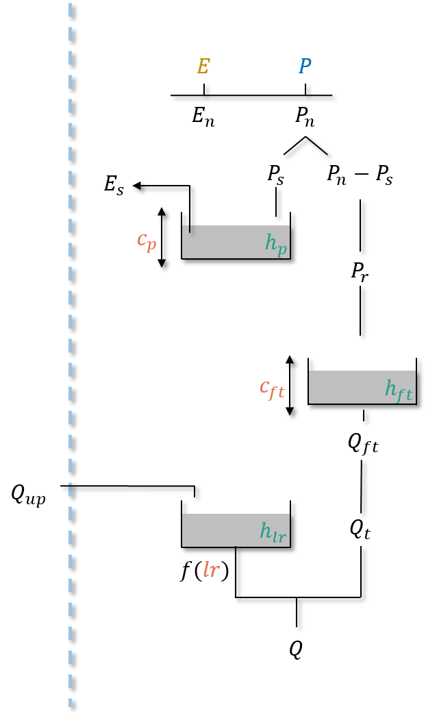
gr-d#
Parameters#
cp: the maximum capacity of the production storage \((mm)\),cft: the maximum capacity of the transfer storage \((mm)\),lr: the linear routing parameter \((min)\).
States#
hp: the relative state of the production storage \((-)\),hft: the relative state of the transfer storage \((-)\),hlr: the absolute state of the routing storage \((mm)\).
Operating#
neutralization of \(P\) by \(E\) to determine a net rainfall \(P_n\) and a net evapotranspiration \(E_n\),
filling (resp. emptying) the production storage by \(P_s\) (resp. \(E_s\)),
\(P_r\) inflows the transfer storage,
\(Q_{ft}\), the outgoing flux of the transfer storage, is the cell flux \(Q_t\),
filling the routing storage by the upstream flux \(Q_{up}\),
computation of the final routed flow \(Q\) at the output of the routing storage.